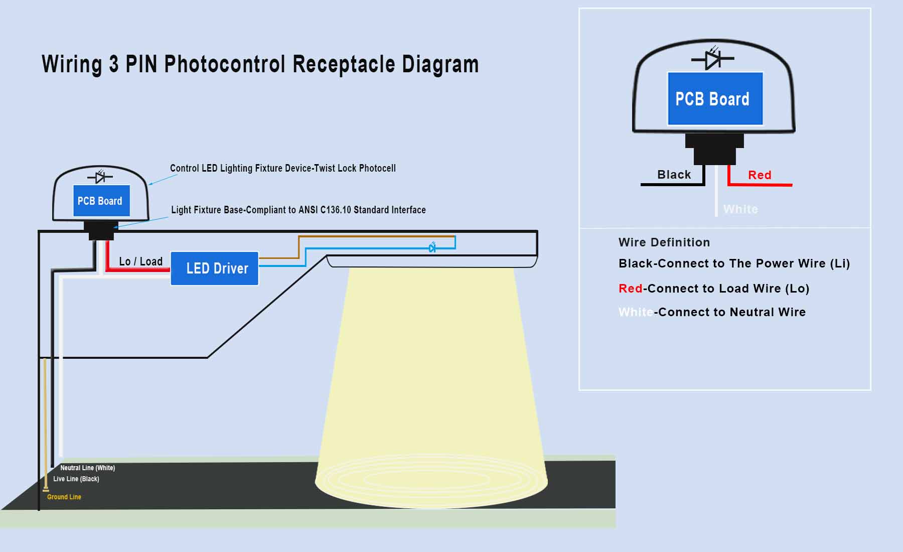
3 Wire Photocells Connect Picture Diagram

How to Mount 3 Wire Photocell Installation Description
1. disconnect the circuit breaker to your outside light. If you do not know which breaker powers your light, turn off all breakers in the building to ensure that power is cut off. Double-check that the power is off by flipping the switch to the outdoor light to make sure it doesn’t turn on.
2.Disassemble the housing that contains your exterior light. You may want to document how it comes apart with photographs so that you can easily put it back together.
3. You should see 3 wires on the photocell. one of the black wires needs to be tapped into your structure’s main power. and one of the red wires needs to connect to the load / LED Driver, then it wiretapped into your light fixture. but the best last important white wire connects between auto-on switch photocontrol and LED Driver.
4. Connect one black wire on the photocell to the black wire that comes from the building (live line). Be sure to twist the exposed copper wire so that it forms a tight connection.
5. Connect the red wire on the photocell to the LED Driver and its lead brown wire on your light fixture, making sure that the copper wire is twisted together completely.
6. Tape your connections completely with electrical tape. Make sure that there are no exposed copper wires.
7. To test the photocell, turn the power back on at the breaker. Make sure that the light switch is in the on position. Cover the photocell with your hand—if the light turns on when the photocell is covered, your photocell is working properly.
8. Finish installing the photocell by putting it into your light fixture and tightly clockwise to twist-lock jointed.
3 Wire Photocell / NEMA 3pin Twistlock Installation Circuits Diagram
Black-connect to the power wire(Li)
Red-Connect to Load wire (Lo)
White-Connect to Neutral wire, and photocell switch, and LED Driver

Post time: Jul-14-2021